Modification types
Transit network modifications
Add trip pattern
The add trip pattern modification allows you to add new trip patterns to your transport scenario. A trip pattern is a set of stops visited in order by a transit vehicle. Often a route will consist of multiple trip patterns, e.g. one for each direction of travel. This modification also offers a bidirectional option to allow a single trip pattern to represent travel in both directions. This may be easier for modes with generally bidirection stations like subways, ferries, or cable cars.
After creating a new modification you will see something like the view below.
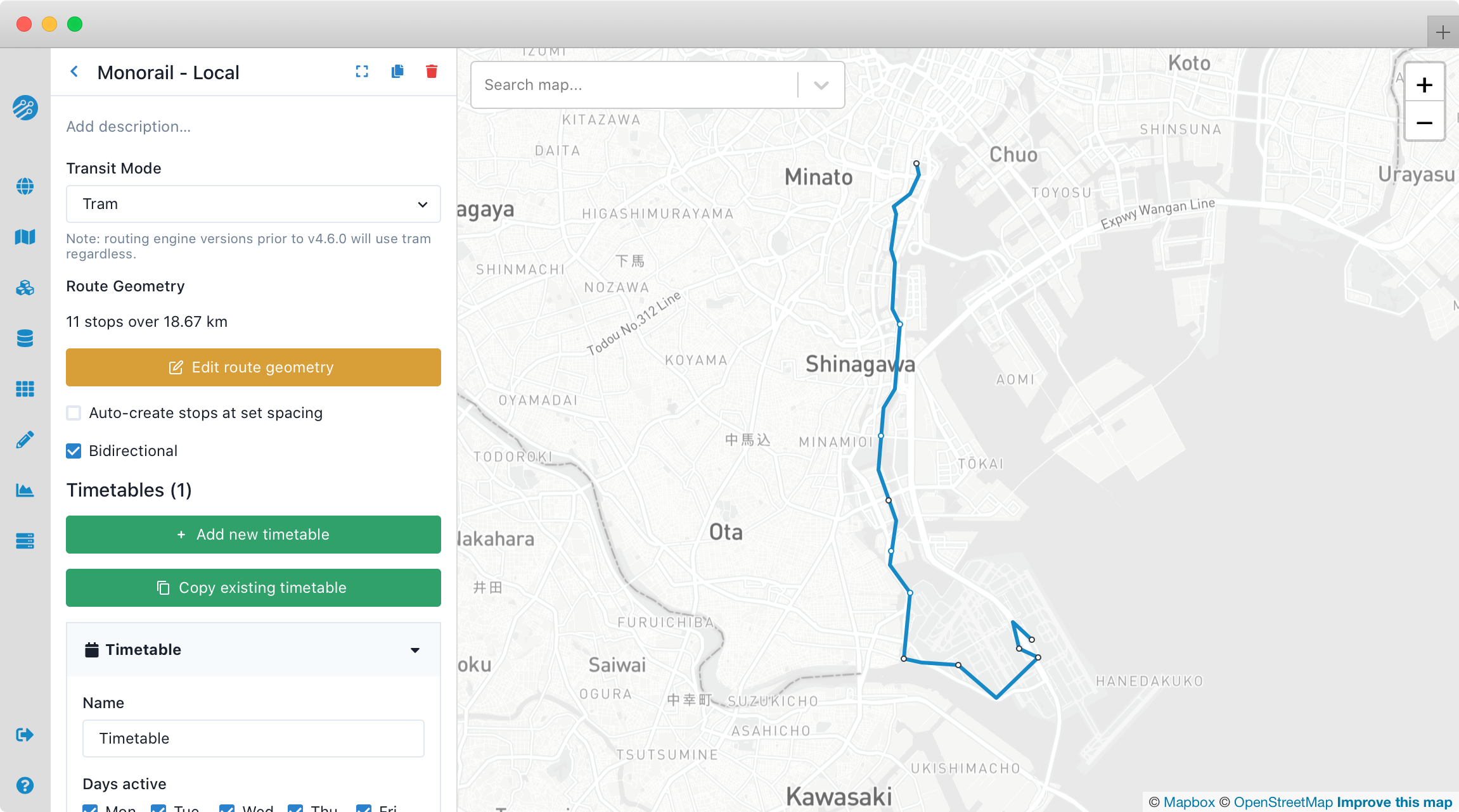
You can set the mode (e.g. bus) and add a description for the modification at the top of the panel. To create an alignment, or to edit the alignment you've previously created, click Edit route geometry
This will activate the map-based route editing mode. You can stop and save your work at any time with: Stop editing
New route alignments are defined by by an ordered set of stops and control points. The actual route taken between these can either follow existing streets or it can take a straight line between points. It is also possible to combine the two options in one route as when a bus runs on the street but then diverts into a planned busway which is not yet part of the street network. The distance between stops is used to estimate segment travel time on the new alignment so it is important to as be as accurate with the alignment as possible.
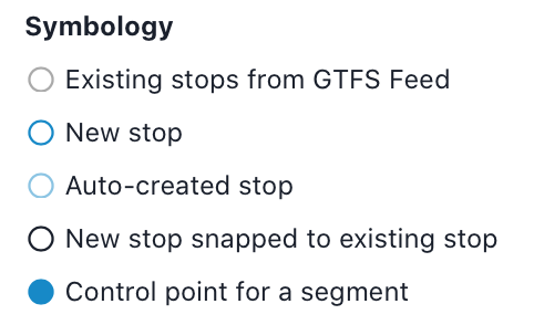
By default when you begin editing a new route, you can click once on the map to place the first stop, then again to place the second stop, and so on. If you click on an existing stop (indicated by a small gray circle), the icon for the new stop will be black and the new transit service will stop at that existing stop. If you click in a place where there is not an existing stop, a new stop (in blue) will be created. In general, we recommend adding stops near walkable streets; stops that are far from walkable streets may be automatically linked to the nearest walkable street in an unintuitive way.
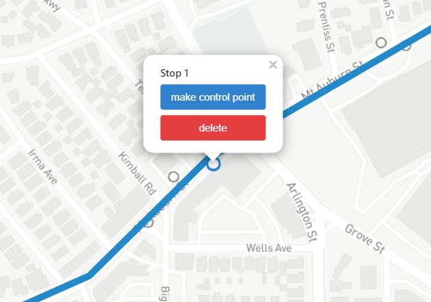
Once created, any stop or control point can be moved by dragging it to a new location. Clicking on a stop gives you the option to delete it, or convert it to a control point through which the route will pass without stopping. Similarly, control points can be converted back to stops or deleted by clicking on them.
You can also insert a stop into the middle of an existing alignment. Simply hover over the any part of the line and you should see a new stop appear below your cursor. Click to add it at that location.
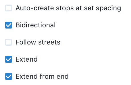
On the panel to the left of the map there are a few options available while editing an alignment. These are described below.
-
Auto-create stops at set spacing: Specifies whether stops should be created automatically at a specified interval along the route. When using this option, you will likely want to define your route alignment with control points rather than stops, however if stops are used new stops will not be added unless the gap between existing stops is sufficiently large. The stop spacing can easily be changed later.
-
Bidirectional: If this option is checked (the default value), vehicles will travel in both directions along the described geometry. If it is toggled off, vehicles will only travel in the direction the line is drawn. Directed alignments can be useful when there are couplets or other aspects of the route that don't follow the same alignment in both directions. Directed alignments are also necessary for phasing.
-
Follow streets: If this option is unchecked (the default value), stops and control points will be connected by straight lines. If it is checked, the route will follow streets. This setting only applies to segments that are actively being edited and will not cause already drawn segments to follow the streets, allowing you to draw part of a route on street and part off-street. The length of each segment is used to estimate travel times between stops, so this feature is very useful for approximating the length of bus/streetcar routes.
-
Extend: If this option is checked (the default), clicking on the map will extend the route forward from the end by adding a new stop in the direction the line was drawn. If you wish to edit segments you already created, by adding stops or control points, it is often convenient to uncheck this option so that stray clicks do not extend the route from one of its termini.
-
Extend from end: When Extend is enabled, this option allows you to specify whether new stops will be added moving forward from the last stop of the route (the default) or backward from the first stop of the route. When this option is unticked, new stops will be added as extensions backwards from the beginning.
-
Snap to existing stops (beta): Experimental feature that adds stops from the baseline GTFS bundle to the new route. This feature adds stops within 20 meters of the alignment, but not more than one stop approximately every 80 meters.
Once you have created an alignment, you'll need to specify when the route runs using a simplified timetable. You can do this by copying a previously created timetable, or by clicking Add timetable
Adjust dwell time
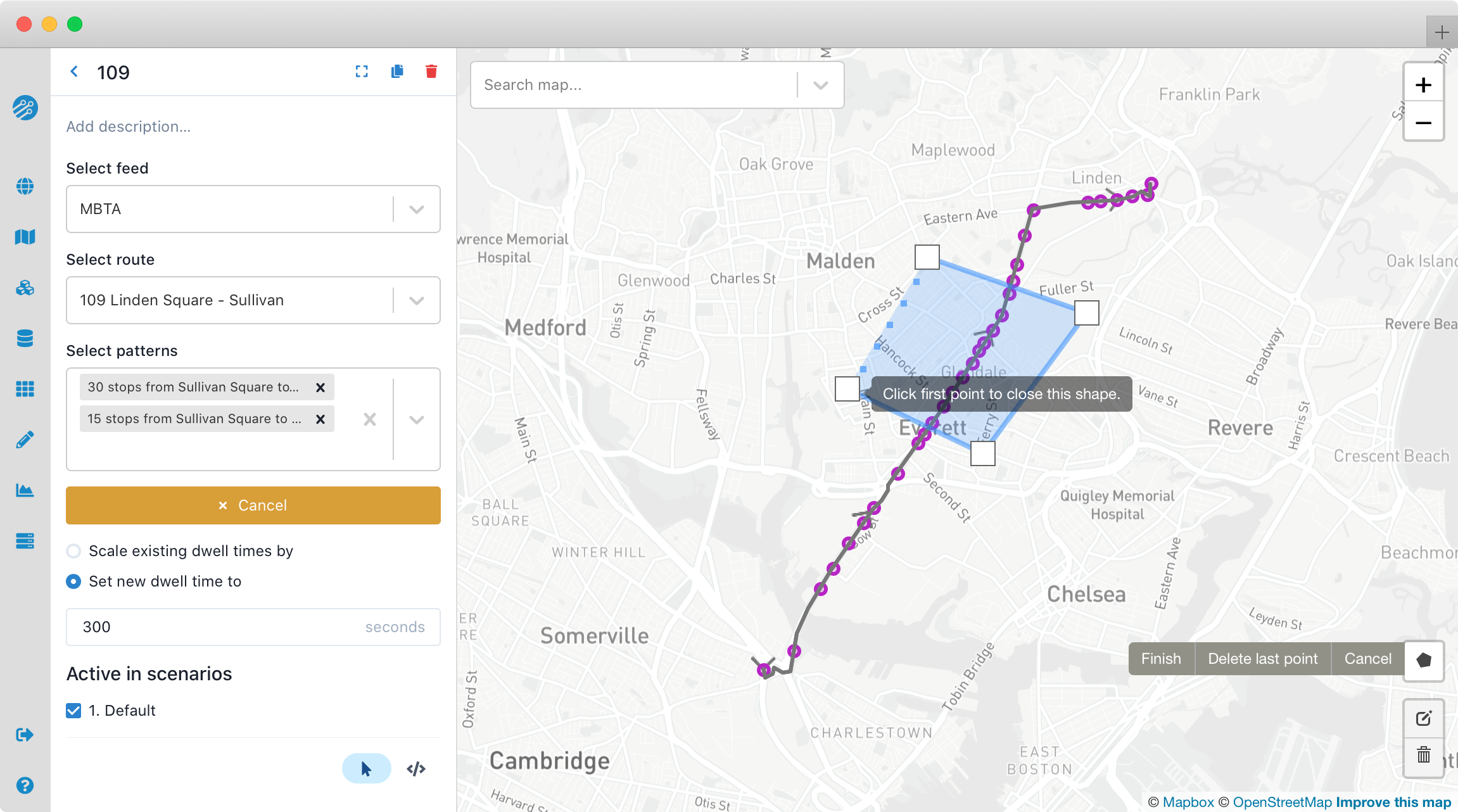
You may also want to adjust the dwell time along a route or at a particular stop, for example to model the effects of off-board fare collection, or the effects of increasing ridership at a particular stop. As with the remove-stops modification, you can select a feed, route and optionally patterns. You can then use the map to select the affected stops (if you skip this step, all stops will have their dwell times adjusted). You can then choose to either enter a new dwell time (in seconds), or scale the existing dwell times (for instance, entering 2 would double existing dwell times).
Unfortunately, the stop_times.txt files of many GTFS feeds use equal arrival_time and departure_time values. For such feeds where many or all dwell times are zero, the scaling approach will not work and dwell times must be set in seconds.
Adjust speed
This modification can be applied to multiple routes, but only one route will be shown on the map.
This modification does not automatically increase frequency in response to the more efficient routes. However, it can be paired with an adjust frequency modification to model such a response.
Sometimes you will want to adjust the speed on an entire route or just a segment of one. For instance you might want to model the addition of bus lanes or an application of transit signal priority. This modification allows you to scale the speed of existing scheduled trips, or segments of them, by a constant factor. It can be applied to whole routes (in which case more than one route may be selected) or to selected segments of a particular route or to just a subset of trip patterns.
You will need to select a GTFS feed, routes and optionally trip patterns if only one route is selected. All trip patterns will be selected by default. Segments can be selected by clicking Select from the toolbox shown in the figure below. This will allow you to begin drawing a polygon selection area on the map. Any segments within this area will be selected when the polygon is closed and selected segments will then render on the map in purple.
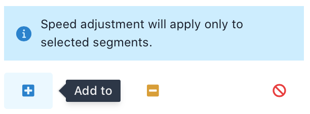
The Select option will begin a new selection and the Add to option will add to the current selection if any. Remove from allows you to select segments to remove from the current selection and Clear un-selects all segments.
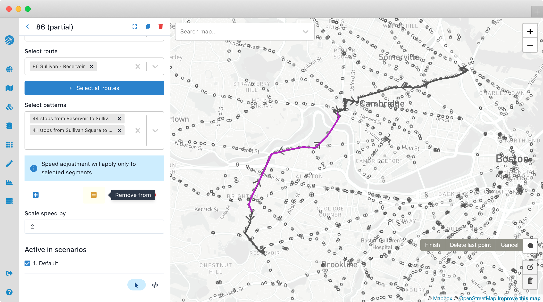
Finally, enter a numeric value in the Scale speed by field --- this is the factor to multiply the speed by. For instance, if you enter 1.3, the speed of vehicles will increase by 30% when traveling between stops. Note however that this modification does not affect dwell times; to model changes in dwell time, see the adjust dwell time modification. It also does not take into account the possibility of increased frequency due to faster, more efficient routes. However, it can be paired with a convert to frequency modification to model that scenario.
Convert to frequency
Often a scenario will include changes to the number of trips per hour on an existing route. We support this using the convert to frequency modification. It works by replacing the scheduled trips for one or more existing trip patterns with frequency based timetables. You can opt either to
- delete all existing trips and replace them with your own timetables or
- replace trips only when the new timetables would be in effect.
The travel and dwell times on the replacement trips are based on those of an existing trip which you can select from the affected trip pattern. The new timetables can make use of phasing to reproduce timed services on branching lines, etc.
First, create a new modification and select Convert to frequency. Give the modification a name; you will likely want to name it after the route you plan to modify.
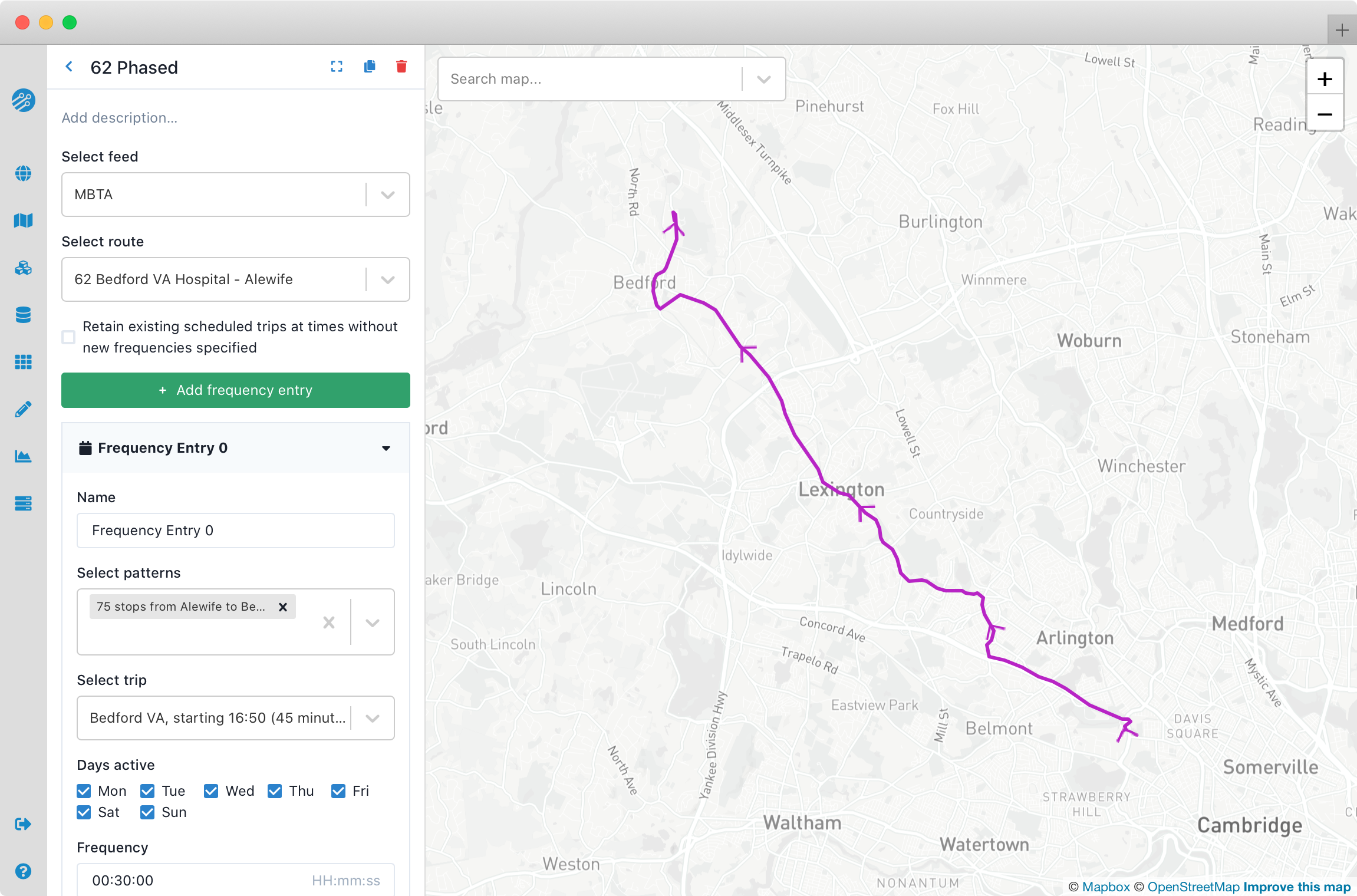
Start by selecting a GTFS feed and then the route from that feed that you want to adjust. You should see all trip patterns for the selected route displayed on the map.
You can choose to remove all existing trips on the route (the default) and start from scratch with new timetables. Or you may choose to retain trips outside the time windows in which you specify frequencies which is useful when you are changing the frequency for only part of the day (e.g. increased weekend frequency) and want to retain the existing scheduled service at other times. This is controlled using the checkbox labeled "Retain existing scheduled trips at times without new frequencies specified".
You then create any number of frequency entries using simple timetables. Within each timetable, you will need to select a single trip pattern from your route, then a particular trip from that trip pattern to be used as a template. Travel times for the new timetable will be based on this template trip so it is important to choose one that is representative. For example, you may want to select one of the slower trips when specifying frequencies during congested peak-hour service.
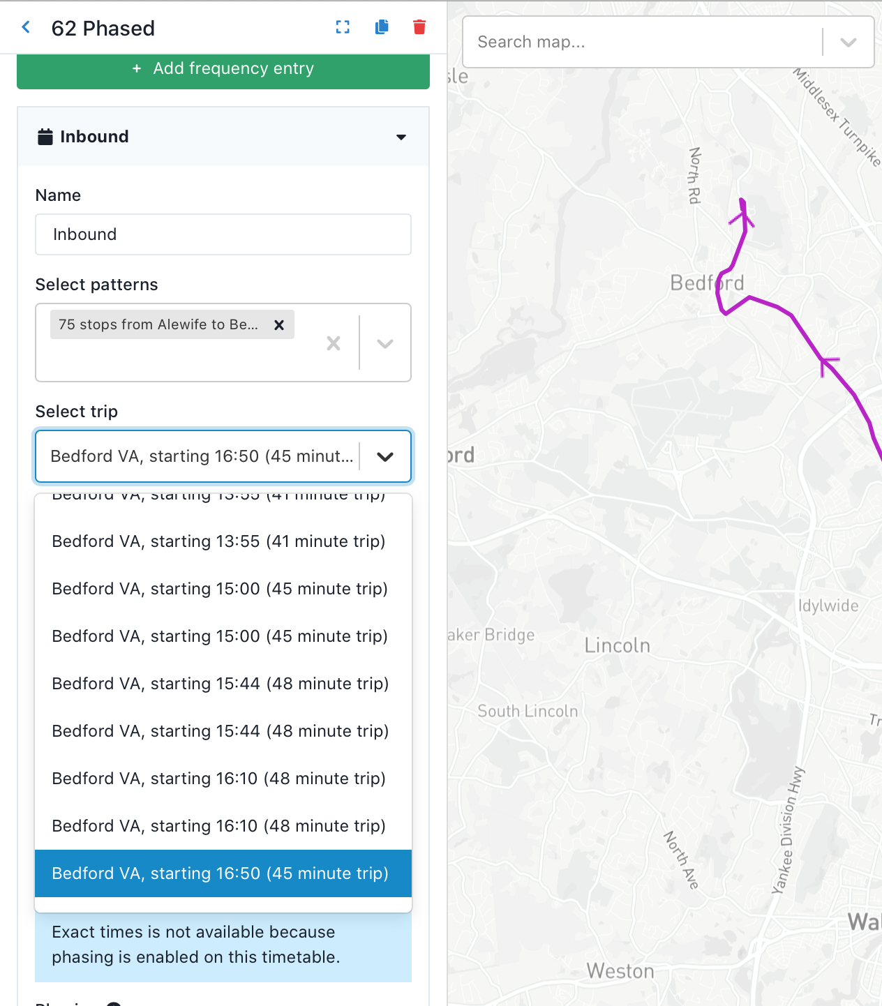
Typically, you will need to create at least two new timetables, one for each direction of travel.
Once converted to a frequency-based route with this modification, any of a route's patterns not represented by a timetable are effectively removed. With "retain trips" set to the default value of false (unchecked), these patterns will be removed at all times of day. With "retain trips" set to true (checked), they will be removed when any frequency entry is active.
Remove stops
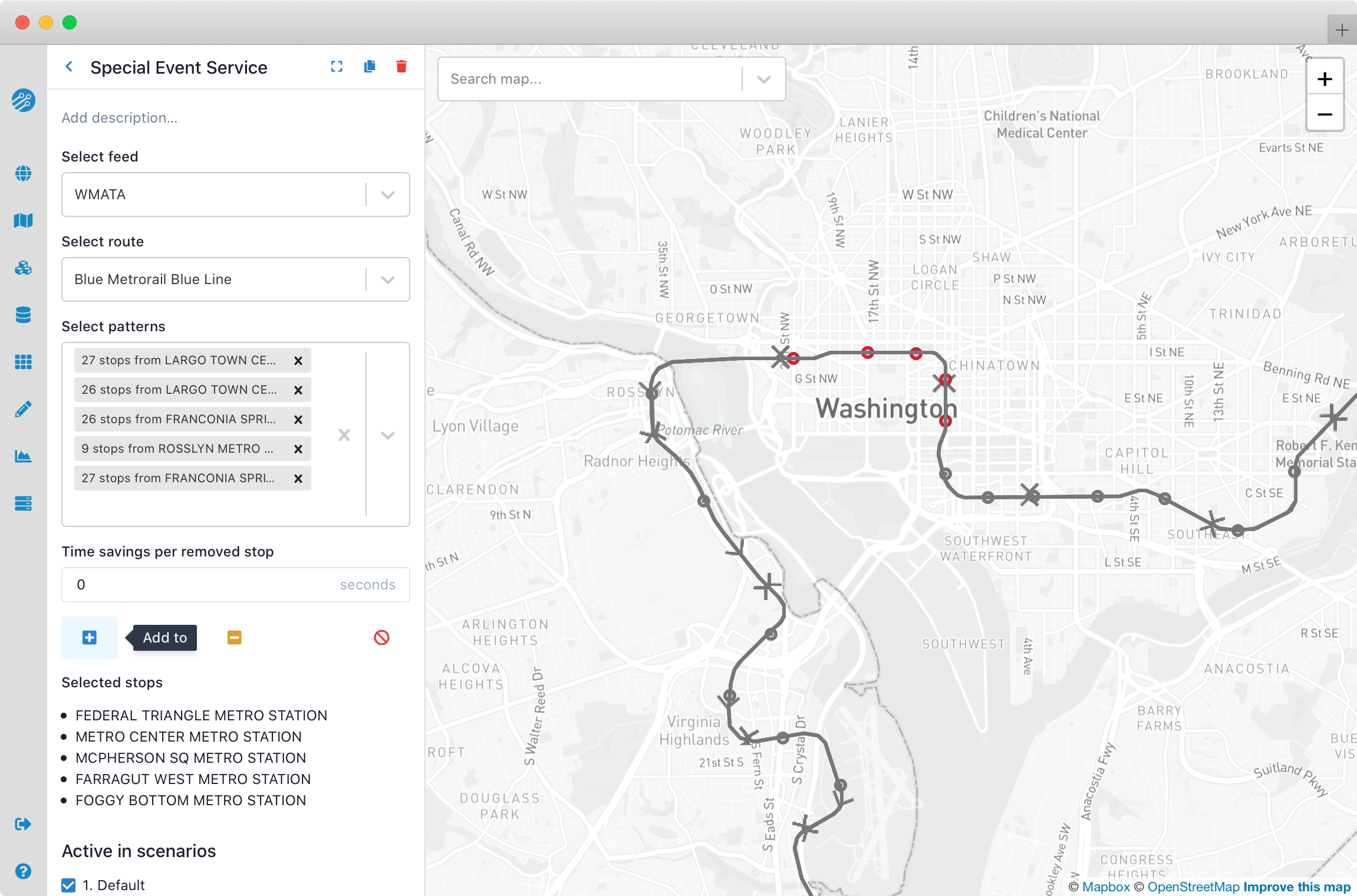
It is also possible to remove some of the stops from a route, while leaving the rest of the route untouched. To do this, create a new remove stops modification, and select a feed, route, and patterns as you did when removing trips. You can then use the map to select which stops to remove. Under "Selection," click "new", "add to," or "remove from" to select new stops to remove, add to the existing selection, or remove from the existing selection. Stops that are selected for removal are listed at the bottom of the modification, as well as being highlighted in red on the map.
You can also specify that you wish to remove a certain amount of time at each removed stop (in addition to the dwell time specified in the original feed, which is automatically removed). This could be used to account for acceleration and deceleration, and can also be used when the original feed does not specify dwell time. This feature is useful when testing the effects of stop consolidation.
When removing the beginning of a route, the dwell times at each stop are removed, as is any time specified to be removed at each removed stop. Any remaining travel time is preserved as an offset from the start of the trip in the original GTFS to the start of trips at the new first stop. This is effectively as if the vehicles were leaving the original terminal at the same time but deadheading past all of the removed stops.
This modification does not take into account the possibility of increased frequency due to more efficient routes. However, it can be paired with a convert to frequency modification to model that scenario.
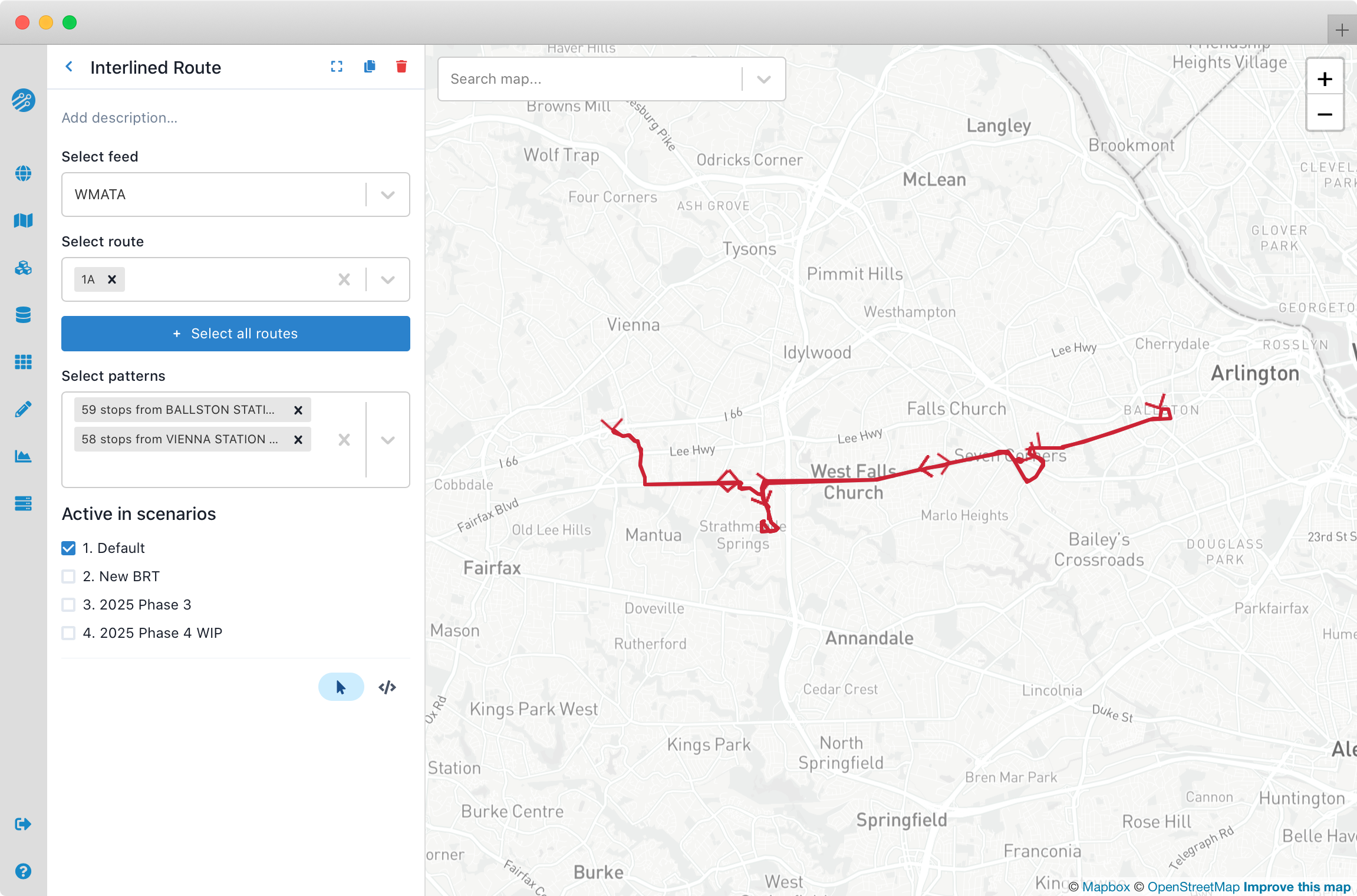
Remove trips
Another common modification is to remove trips. The most common use is to remove entire routes, but it is also possible to remove only specific trip patterns on a particular route. In order to remove trips, create a new remove trips modification, and select a GTFS feed, route, and optionally the trip pattern of the trips to be removed. All trips on this route/pattern combination will be removed and the route will be shown in red on the map. You can select multiple routes to remove, but only one will be shown on the map.
Reroute
This modification type can be used to represent detours, extensions,and curtailments. When creating a reroute modification, you first select a GTFS feed, route, and trip patterns. Once trip patterns are selected, you then select a stop at which the reroute alignment will start, or a stop at which the reroute alignment will end, or both, by clicking Select then clicking an existing stop on the baseline pattern.
Note that every selected pattern must stop at the selected start-of-reroute stop and end-of-reroute stop. For example, consider these three patterns:
- A-B-C-D-E
- A-B---D-E
- A---C-D-E
If stop B is selected as the start-of-reroute, and stop D is selected as the end-of-reroute, patterns 1 and 2 can be included in the reroute modification. Do not select Pattern 3, because it does not stop at the selected start-of-reroute stop.
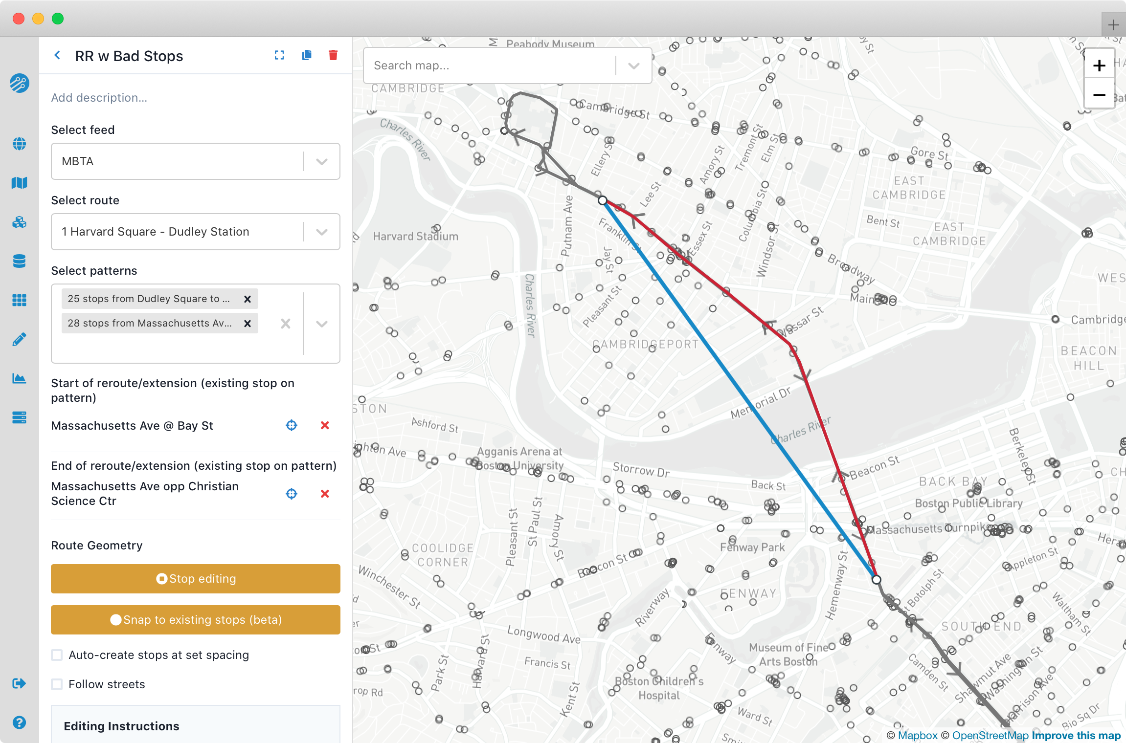
Once a start or end stop is specified, you can add and modify segments by clicking the Edit route geometry button, then clicking on the map. Editing behavior is similar to editing mode for adding trip patterns though with some options fixed depending on whether the route is being extended in either direction, or if the reroute is happening in the middle of the alignment.
- If only the "start of reroute/extension" is set, new stops and segments will be added extending forward from the selected stop on the baseline pattern ("Extend from end" turned on).
- If only the "end of reroute/extension" is set, new stops and segments will be added extending backward from the selected stop on the baseline pattern ("Extend from end" turned off).
- If both are set, the new segment between the stops cannot be extended, but it can be modified by clicking on it to add stops and control points ("Extend" turned off).
A reroute modification can apply to multiple trip patterns in a single direction as long as the patterns all contain the start and end stop in order; you will generally need to create one reroute modification for each direction of the route.
A few examples should help to illustrate how this modification works. Consider a baseline pattern passing through stops A -> B -> C -> D:
- To curtail this pattern at stop C, eliminating service to stop D, select C as the "start of reroute/extension."
- To reroute this pattern from C to another stop X instead of D, select C as the "start of reroute/extension," activate route editing, and click on stop X to add a segment from C -> X. Speeds and dwell times can be set on this added segment. Baseline speeds and dwell times between A and C are not affected.
- To extend this pattern backward, to originate at a stop Y, select A as the "end of reroute/extension," activate route editing, and click on stop Y to add a segment from Y -> A. Speeds and dwell times can be set on this new segment. Baseline speeds and dwell times between A and D are not affected.
- To detour this pattern so that it serves a stop Z between B and C, select B as the "start of reroute/extension", select C as the "end of reroute/extension", activate route editing, click on the new segment to add a stop, and drag the added stop to Z. Speeds and dwell times can be set on this new segment. Baseline speeds and dwell times between A and B, and between C and D, are not affected.
Street network modifications
Simple modifications affecting the street network were introduced in June 2020 and are currently experimental. Later releases will likely change some aspects of these modifications.
For detailed editing of streets and intersections, it is often preferable to use an OSM editing tool (e.g. JOSM) to prepare inputs for Conveyal, rather than relying on these simple modifications.
Both street modification types require specifying whether access is allowed for walking, cycling, and driving.
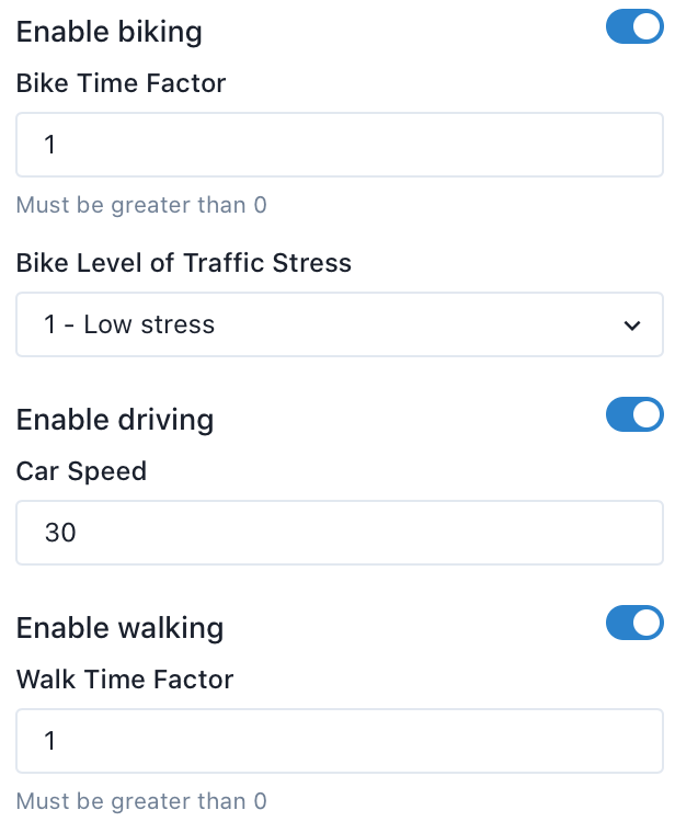
If access for a given mode is enabled, you will have options to set corresponding properties.
The default walk time factor and bike time factor values of 1 will have no effect on results. For baseline street networks built with custom generalized cost or impedance values, values other than 1 can be set, which will scale the amount of time it takes to traverse these links. For example, if you are routing by "perceived" time, a pleasant street might have a walk time factor less than 1, while a high-traffic unpleasant street might have a walk time factor greater than 1. Contact your support team for more details.
Bike level of traffic stress can be used to set the level of traffic stress for street links added or modified by the modification. Streets beyond the Maximum level of traffic stress set in an analysis will be traversed at walking speed. See here for more details.
Finally, if driving is enabled, you must enter a constant speed in kilometers per hour.
Add Streets
The add streets modification allows you to add new links to the street network, making new walking, cycling, and/or driving connections. Each new street or set of streets is characterized by mode-specific access restrictions and travel impedances. Each modification allows one or more new streets to be drawn on the map and attributes of these streets are set at the level of the modification. This means a modification can include several new streets each with the same properties. For example you might use one modification to add several footbridges to your network and another for a new network of shared-use bike paths.
Once you've created the modification, you can add streets to the map by clicking the line icon on the right side of the map. This allows you to draw a series of line segments (a polyline), which will be connected to the baseline network. For each polyline, the start and end nodes are each connected to the nearest edge in the baseline network (up to a limit of 1600 meters). Add-street polylines are not directly connected to each other. To finish a polyline, click again on the final point or select "finish" from the editing menu.
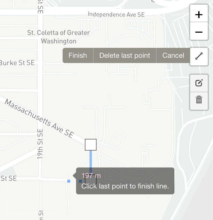
To create a line connecting to the existing network at several points, you will need to create multiple lines. Click the line icon again to start drawing a second polyline starting from the same point.
You can also edit previously drawn lines by clicking on the edit layers icon. This will allow you to add, move, or delete nodes. To delete a whole line, click on the trash can icon and then click somewhere on the line. Be sure to hit save when you are satisfied with your edits.
Modify Streets
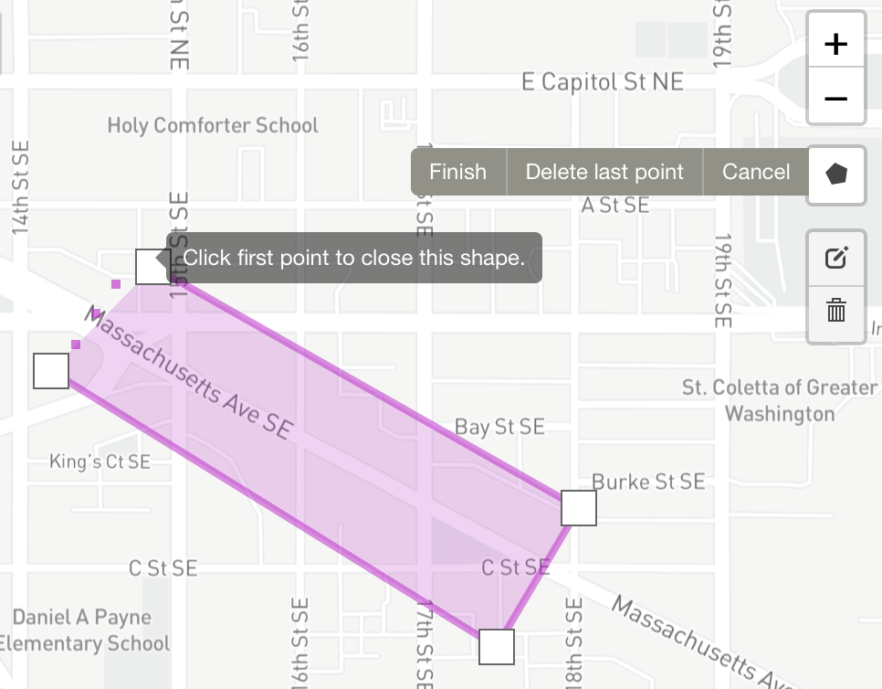
This modification allows you to assign new access and impedance properties to existing streets in your baseline network. Rather than selecting individual streets, it uses a polygon selection to apply the modification to all street edges that are entirely within the selected area. This is useful for applying changes to areas or corridors. As an example, you might use this to identify a neighborhood or corridor where traffic calming measures will be implemented and model this by reducing bicycle traffic stress and decreasing driving speeds or eliminating automotive access altogether. Similar to the Add Streets modification, properties are set at the level of the modification, and multiple areas can be specified. Thus, separate modifications are needed to specify different types of areas.
To draw a polygon on the map, click the polygon icon and begin clicking on the map. Clicking the first point again will close the polygon and nodes can be added, moved, and deleted once the shape is drawn by clicking on the edit option. Overlapping polygons are not yet supported.
When analyzing a scenario with this modification type, the analysis panel will display how many network edges were affected (out of a number of "candidate" edges within the rectangular bounding box of the modification).
Custom
Custom modification types allow experimenting with certain features that are not yet widely supported. Contact your support team before trying these types; an improper configuration may produce errors during analysis.
Pickup delay
This modification type allows modeling on-street modes that serve defined zones with specified service levels, such as shared scooters or ridehail services. It requires an uploaded geojson polygon data source with id and wait (in minutes) attributes for each feature. For example, within a polygon with id: "Downtown" and wait: 10, the routing engine would allow people starting journeys in the "Downtown" polygon to wait 10 minutes then proceed by car. Custom JSON settings allow setting different modes, default wait times, designated transit stops for pickup/dropoff, etc. For example, if your uploaded data source has a pickup/drop-off zone polygon (ArtesiaZone) and two station zone polygons that are buffers around fixed-route transit stops (AvalonStation and ComptonStation), you can add this to the custom JSON:
"stopsForZone":{"ArtesiaZone":["AvalonStation","ComptonStation"]}
This setting will prevent point-to-point travel in the Artesia zone, and only allow on-demand rides as first-/last-mile connections to fixed-route transit at the stops in the two specified station zones.
For more details and other custom configuration options, see the R5 source code or contact your support team.
Road congestion
This modification type lets you set a scale factor for car speed within features of a geojson polygon data source. It requires an uploaded geojson polygon data source with scale and priority attributes for each feature. For example, within a polygon with name: "Downtown", scale: 0.60, and priority: 1, default car speeds in the "Downtown" polygon would be multiplied by 0.60. Custom JSON settings allow overriding the default attribute names, setting a default scaling value to be applied outside of the supplied polygons, etc. For more details, see the R5 source code or contact your support team.
Custom LTS
For custom cycling Level of Traffic Stress, upload and select a linear shapefile data source with an lts attribute for each feature. For now, this modification type cannot be applied with bike + transit analyses.
Raster cost
Conveyal provides certain cost functions that translate exposure to a raster surface along a network edge to modified traversal time for that edge. For example, to account for slope in walking times using Tobler's hiking function: download an elevation raster layer (e.g. from the National Elevation Dataset), load it as a data source, create a custom streets modification referencing the data source, and set "costFunction": "TOBLER" in the custom modification JSON. An alternative function, "costFunction": "MINETTI" is based on Minetti et al. (2002).
Modification order
You can apply multiple modifications of different types to the same transit route or section of the street network. In a given scenario, modifications are applied in the order described below.
Modify Streets modifications are applied first, followed by Add Streets modifications. So the characteristics of added street links are not affected by overlapping Modify Streets modifications (e.g. the car speed specified for an added street will not be scaled by the speed scaling factor in a Modify Streets modification that contains it.) This also allows removing streets and then replacing them within a single scenario.
Transit modifications are then applied in the order:
- Adjust Speed
- Adjust Dwell Time
- Remove Stops
- Reroute
- Adjust Frequency
- Remove Trips
- Add Trips